How to build a simple but cool IR (Infra Red) receiver.
The wire and the capacitor
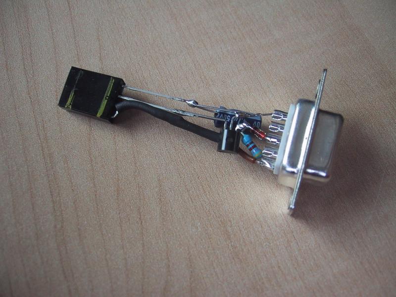
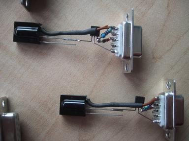
We now mount the wire from the data output of the IR receiver to the DTS of the serial connector, and the capacitor between GND and the output of the voltage regulator.[-]
The wire has to be cut so it can easily go from the data pin of the IR receiver to the first pin of the serial connector. Then we solder it on the data pin *only*.
[-]
We put then a piece of the thermal tube to protect the data line. Remember to "burn" it a bit so it will stay against the wire.

[-]
Is it possible now to solder the other end of the wire to the first pin of the serial connector.

[-]
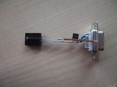
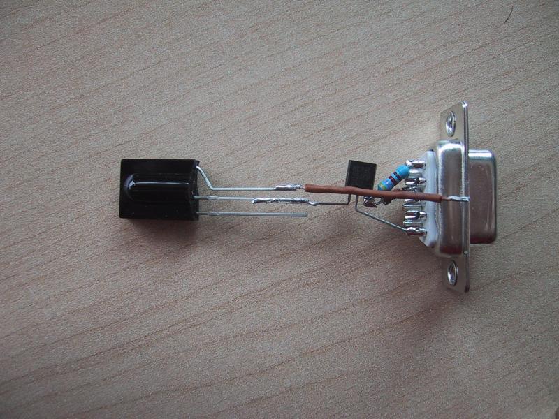
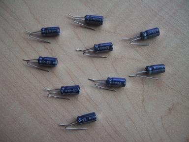
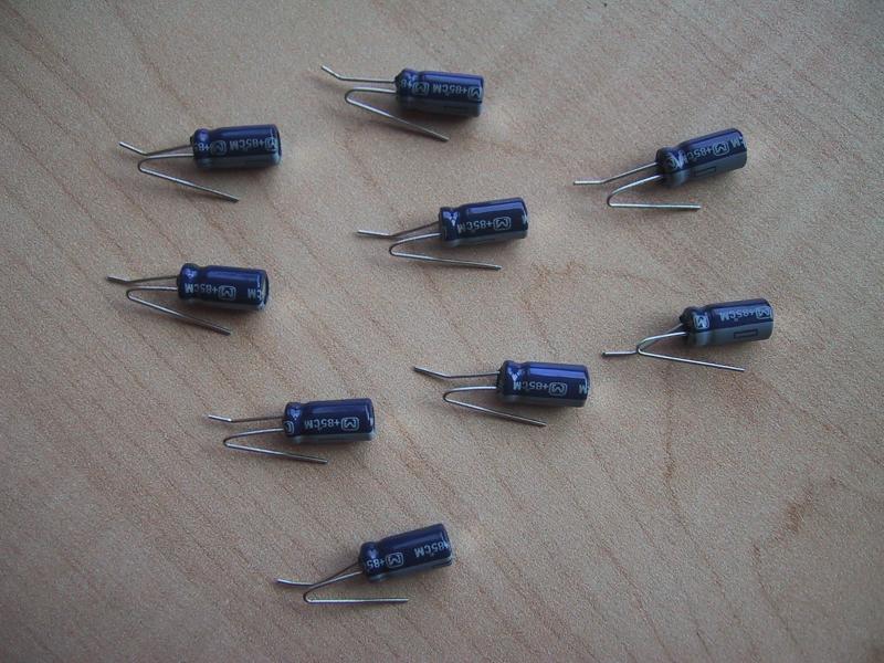
This is a very delicate work: you should try to bend the pins of the capacitor like in the picture. Pay attention that electrolitic capacitors are polarized: in simple words, there is a positive and a negative pin.
[-]
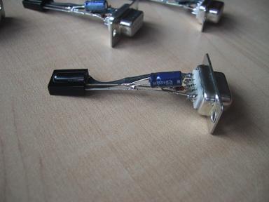
Look at the picture to understand how to mount the capacitor. The positive pin has to be soldered together with the output of the voltage regulator and the power input line of the IR receiver. The negative pin will act as a bridge to connect the ground of the IR receiver together with the ground of the regulator.

[-]
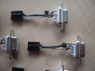
I suggest you to solder first the negative pin of the capacitor to the ground of the receiver, then to the ground of the regulator. At this point you'll have to adjust a bit the position of the positive pin to easily solder it on its place. After this, bend the capacitor so it "lays" on the circuit making it easy to fit inside the serial case.